The Basic Function of a Flow Control Orifice
A flow control orifice is a method of setting the throughput in a fluid path. In the same principle as a dam in a river, a flow control orifice will restrict the movement of fluid passing through it. The upstream supply of fluid is greater than the flow rate through the orifice. That way, the restriction provided by the flow control orifice will always determine the flow rate.
Flow Control Orifices Used in Gas or Liquid Control Applications
A flow control orifice is capable of controlling fluids which include both gas and liquids. It is important to understand that the viscosity of the fluid, along with the orifice size, will determine the flow rate. In other words, while it is true that an orifice can control either liquids or gases, the actual flow rate for a given orifice size will change with the fluid flowing through it. So, if the fluid flowing through the orifice remains the same, an orifice will provide stable and repeatable flow control.
Flow Control Orifices in a System
System designers will use a flow control orifice to set the flow rate at a known level in a fluid circuit. There may be a single orifice to control the overall flow rate in a system, or there may be a flow control orifice in each circuit of the system. It depends on the goals of the design. Here we will explore some common design practices.
Predictability in Mass Production
A flow control orifice can provide peace of mind to a system designer, allowing them to rest assured that the differences in tolerances and variations between components of the system cannot accumulate and lead to malfunctions.
Flow Ratio Between Circuits
A system designer can use flow control orifices of varying sizes to create circuits that deliver a ratio. For instance, a 2:1 flow ratio could be achieved by using 2 orifices where one has twice the flow rate as the other. Any number of combinations can be achieved.
Flow Balancing Parallel Circuits
When a system has many parallel circuits, it can be difficult to get equalized flow in each circuit path. The difficulty comes from practical matters such as tube routing, circuit layout, inactive circuits, and tolerance stack-up. By adding a flow control orifice in each parallel circuit, the system can be flow-balanced.
Correcting Flow Rates for Material Viscosity
Each fluid has its own viscosity, or resistance to flow. Since viscosity is a determining factor in the flow rate through an orifice, if an OEM (original equipment manufacturer) wants to set a flow rate for a particular fluid, an orifice may be specified to achieve it for each specific fluid. Fluid viscosity through an orifice varies mainly by material characteristics and temperature.
Spray Nozzles
Spray nozzles are a special type of flow control orifice, where the exiting fluid pattern is critical to the application as well as the flow rate. An application may require a tight stream, like a squirt gun, or a spray pattern, like a cone. A designer will determine several characteristics that are important to the application of a spray nozzle such as flow rate, exit angle, and spray pattern.
Flow Control Orifice Products
There are different embodiments of flow control orifices, depending on how they will be incorporated into the design and production of the final product. Some of these embodiments are stocked as off-the-shelf products. Others are custom-made for the application with close communication about the specific requirements.
Orifice Restrictor
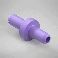 Orifice restrictors are used in all types of miniature flow control applications. They are commonly made from plastic in high volumes. This group of products includes inline orifice restrictors that have tube fittings on each end. Orifice restrictors may also be incorporated into threaded fittings or inserted into larger assemblies. Learn more.
Precision Orifices
High-volume production relies on the idea of interchangeability. A century ago, Henry Ford famously used this idea to develop his assembly lines. Today, it is a foregone conclusion that parts of the same part number will be interchangeable. This is achieved through dimensional tolerancing and quality systems to monitor the manufacturing process. The term precision orifice differentiates a hole that any machine shop can produce via standard machining methods versus a flow control orifice that is made and monitored with a flow tolerance constraint. Learn more.
Directional Flow Control – Orifice Check Valve
Directional flow controls are a combination of two products: a flow control orifice and a check valve. When a circuit must have a higher flow rate in one direction and a controlled flow rate in the opposite direction, a combination of a flow control orifice in parallel with a check valve can be used. The system is simplified by using the combination of both products to achieve the same result. Learn more.
System Design Examples and Applications
Where Are Flow Control Orifices Typically Used?
Applications for flow control orifices are always growing. As new industries develop, the use case for orifices continues to expand. We have just recently started to list out the applications for orifices. Check out this blog for some examples.
What Does it Look Like to Implement a Flow Control Orifice Into a System?
Want to see flow control orifices in action? In this blog, Air Logic uses a model Corliss engine to demonstrate how these products work. The model brings the flow control principles to life in a fun and engaging way. How to Control Your Device With Flow Restrictor Orifices
Find the Right Orifice Size for Your Application
What Does Orifice Size Really Mean?
“Orifice size” is typically used as short-hand for flow constant (Cv) in the world of flow control orifices. That is because the orifice diameter is the main factor used to determine the flow rate. The flow will change in relation to the size of the flow control orifice. So, a larger flow control orifice will have more flow, and vice versa. It should be noted that other factors, such as the orifice aspect ratio (length vs. diameter), also determine the flow rate but not to the same magnitude as the diameter.
How to Find the Right Orifice Size for an Application
Calculate the Right Orifice Size
In order to calculate the right orifice size for any application, several factors must be known, such as target flow rate, fluid viscosity, upstream and downstream pressure, and temperature. This Flow Calculator makes it easy to find the right size. It also shows the equation for flow through an orifice. Additionally, you can override the preset values to make your own flow calculations.
Bench Testing With Samples
Whether you started with a calculation or just a hunch, bench testing to find the right flow control orifice size is an important step in product development. At Air Logic, we want to assist you in the product development phase, so you can request a single part number as a sample or ask for a kit of sample orifices.