Posted by Cayla Julius on | Comments Off on Material Combination Evaluation: Nylon/Buna
In many fluid handling systems, a combination of tough plastic and resilient rubber is used to create reliable, cost-effective fittings. One common pairing is Nylon (polyamide) for the rigid component and Buna-N (nitrile rubber) for the elastomer seals. Nylon offers strength, light weight, and chemical resistance, while Buna provides flexible sealing and compatibility with oils and fuels. The key properties of these materials allow this combination to fit so well in various markets.
Properties and Attributes of Nylon & Buna
Chemical Compatibility: Both Nylon and Buna excel in petroleum-based environments. Nylon is generally resistant to oils, gasoline, diesel, mineral spirits, and many other hydrocarbons. This makes it ideal for fluid connectors and housings carrying fuel, oil, or air. Buna similarly offers excellent resistance to petroleum oils, fuels, hydraulic fluids, and even water and alcohols. Buna is a widely used elastomer due to the resistance to these materials without swelling or degrading.
Temperature Range: Nylon and Buna-N both perform well in moderate temperature ranges typical of engines and industrial equipment. Standard nylon can operate down to around -20 °C before it becomes brittle, and up to roughly 120 °C. Nitrile rubber’s working range is similar, typically about -35 °C on the low end, to 120 °C on the high end. Both materials will degrade if pushed beyond their limits (Nylon can deform with high heat, while Buna will harden or crack over extreme cold), but within their ranges they maintain good performance.
Longevity and Reliability: Nylon is a durable engineering plastic. It resists abrasion and has high mechanical strength. Nylon also does not rust or corrode like metal, which helps longevity. Buna-N rubber, for its part, is valued for its ability to retain its shape under compression, high tensile strength, and excellent abrasion resistance. Together, these properties translate to long-term reliability. A Nylon/Buna fitting can endure years of vibrations, temperature swings, and pressure cycles in industrial or mechanical settings.
Environmental Compliance: Engineers today must consider regulations like RoHS and REACH when selecting materials. Fortunately, Nylon and Buna generally meet these requirements. Additionally, since neither Nylon or Buna contain any of the designated “conflict minerals” (tungsten, tin, tantalum, or gold), manufacturers can typically declare parts made of these materials to be conflict-mineral free.
Limitations and Caution Areas
Even great materials have their weaknesses. When applying Nylon/Buna components, engineers should keep the following limitations in mind.
Moisture Absorption in Nylon: Most nylons are hygroscopic, meaning they absorb moisture from the environment. Over time, nylon parts can swell and change dimensions. Mechanically, water acts as a plasticizer in nylon, making it softer and more flexible (which can actually increase impact resistance) while reducing its stiffness. Thankfully, this effect is reversible. If the part dries out, it shrinks back. To mitigate issues, Air Logic uses Nylon 6/6 to minimize moisture absorption.
Chemical Incompatibilities of Buna-N: Nitrile rubber is a great general-purpose elastomer, but it does not hold up well against certain chemicals. Notably, strong polar solvents and strong oxidizing agents will degrade standard nitrile. The polymer chains in Buna can be broken or chemically altered by these aggressive media, leading to softening, cracks, or loss of elasticity. Always check a chemical compatibility chart if there’s any doubt.
Common Applications and Market Fit
Given their attributes and limitations, the Nylon + Buna combination is a sensible option in quite a few places. This pairing hits a sweet spot of performance and cost that suits many fluid systems.
Automotive and Small Engine Systems
The automotive industry has widely embraced Nylon and Buna in fuel, oil, and air handling systems. Modern cars often use nylon fuel lines and connectors instead of metal. Nylon is lightweight, cheap, and corrosion-free, yet holds up well under fuel pressure. These Nylon components paired with Buna O-rings or gaskets ensure a leak-proof seal for gasoline or diesel. The combination of a Nylon structural part with nitrile seals provides a rugged assembly at a fraction of the weight of metal alternatives. This pairing can be found from lawnmower fuel tank fittings to automotive evaporative emission connectors. The key is that these applications involve petroleum fluids and operate within moderate temperatures – a perfect fit for the materials’ capabilities.
General-Purpose Industrial Fluid Systems
In industrial settings, Nylon and Buna often team up in fluid connectors, couplings, and valves for air, water, and mild chemicals. Nylon’s strength and machinability allow it to be made into threaded fittings, hose barbs, quick-connect bodies, and even valve components. For example, Air Logic’s swivel fittings and needle valves utilize the pairing with a Nylon body and Buna O-Ring to create high-quality seals. Various applications benefit from the chemical compatibility. Nylon and Buna-N together can handle oil, many solvents, compressed air, water, and so on without corrosion or significant degradation. An all-metal fitting with a fluoroelastomer seal might outperform Nylon/Buna-N in extreme conditions, but for general-purpose use, the latter often provides perfectly adequate performance at a much lower cost. One caution in industrial use is to mind the limitations of the pair. But for pneumatics, fuel dispensing, lubricating oil systems, and mild chemical handling, the Nylon + Buna combo is a proven ideal choice.
Cost-Sensitive Consumer & Equipment Products
This material pair is found in many consumer products and light equipment, where keeping costs is crucial. Nylon and Buna-N are relatively inexpensive raw materials, especially compared to alternatives like Teflon or fluoroelastomers. Manufacturers of things like pressure washers, garden sprayers, and fuel tanks often use Nylon plastic parts with nitrile seals. For example, a water filter housing might be Nylon with a nitrile O-ring, or a low-cost fuel pump in a generator might use Nylon fittings sealed by nitrile gaskets. By using this combo, product designers hit an ideal mix of adequate performance at minimum cost. Both materials are readily moldable and work with standard manufacturing processes. Environmental compliance is another plus in consumer goods.
Conclusion
The combination of a Nylon plastic component with a Buna-N rubber seal is a time-tested solution in fluid handling. This pair works best with petroleum oils, fuels, air, and water-based fluids, within moderate temperatures, and with some care taken to avoid known pitfalls like moisture swelling or ozone exposure. When applied appropriately, Nylon fittings and Buna-N seals offer long-lasting, reliable service. Whether that’s in the fuel system of your car, the compressor in your shop, or the pump in your backyard sprinkler. They exemplify a practical balance of properties that suits countless general-purpose uses.
In summary, Nylon and Buna-N is a versatile material combination. One that continues to enable affordable and dependable fluid handling solutions across industries. By understanding their properties and limitations, you can confidently specify these materials in your designs, achieving performance needs while keeping an eye on cost and compliance.
Posted by Cayla Julius on | Comments Off on Understanding Flow Control Orifices
The Basic Function of a Flow Control Orifice
A flow control orifice is a method of setting the throughput in a fluid path. In the same principle as a dam in a river, a flow control orifice will restrict the movement of fluid passing through it. The upstream supply of fluid is greater than the flow rate through the orifice. That way, the restriction provided by the flow control orifice will always determine the flow rate.
Flow Control Orifices Used in Gas or Liquid Control Applications
A flow control orifice is capable of controlling fluids which include both gas and liquids. It is important to understand that the viscosity of the fluid, along with the orifice size, will determine the flow rate. In other words, while it is true that an orifice can control either liquids or gases, the actual flow rate for a given orifice size will change with the fluid flowing through it. So, if the fluid flowing through the orifice remains the same, an orifice will provide stable and repeatable flow control.
Flow Control Orifices in a System
System designers will use a flow control orifice to set the flow rate at a known level in a fluid circuit. There may be a single orifice to control the overall flow rate in a system, or there may be a flow control orifice in each circuit of the system. It depends on the goals of the design. Here we will explore some common design practices.
Predictability in Mass Production
A flow control orifice can provide peace of mind to a system designer, allowing them to rest assured that the differences in tolerances and variations between components of the system cannot accumulate and lead to malfunctions.
Flow Ratio Between Circuits
A system designer can use flow control orifices of varying sizes to create circuits that deliver a ratio. For instance, a 2:1 flow ratio could be achieved by using 2 orifices where one has twice the flow rate as the other. Any number of combinations can be achieved.
Flow Balancing Parallel Circuits
When a system has many parallel circuits, it can be difficult to get equalized flow in each circuit path. The difficulty comes from practical matters such as tube routing, circuit layout, inactive circuits, and tolerance stack-up. By adding a flow control orifice in each parallel circuit, the system can be flow-balanced.
Correcting Flow Rates for Material Viscosity
Each fluid has its own viscosity, or resistance to flow. Since viscosity is a determining factor in the flow rate through an orifice, if an OEM (original equipment manufacturer) wants to set a flow rate for a particular fluid, an orifice may be specified to achieve it for each specific fluid. Fluid viscosity through an orifice varies mainly by material characteristics and temperature.
Spray Nozzles
Spray nozzles are a special type of flow control orifice, where the exiting fluid pattern is critical to the application as well as the flow rate. An application may require a tight stream, like a squirt gun, or a spray pattern, like a cone. A designer will determine several characteristics that are important to the application of a spray nozzle such as flow rate, exit angle, and spray pattern.
Flow Control Orifice Products
There are different embodiments of flow control orifices, depending on how they will be incorporated into the design and production of the final product. Some of these embodiments are stocked as off-the-shelf products. Others are custom-made for the application with close communication about the specific requirements.
Orifice Restrictor
Orifice restrictors are used in all types of miniature flow control applications. They are commonly made from plastic in high volumes. This group of products includes inline orifice restrictors that have tube fittings on each end. Orifice restrictors may also be incorporated into threaded fittings or inserted into larger assemblies. Learn more.
Precision Orifices
High-volume production relies on the idea of interchangeability. A century ago, Henry Ford famously used this idea to develop his assembly lines. Today, it is a foregone conclusion that parts of the same part number will be interchangeable. This is achieved through dimensional tolerancing and quality systems to monitor the manufacturing process. The term precision orifice differentiates a hole that any machine shop can produce via standard machining methods versus a flow control orifice that is made and monitored with a flow tolerance constraint. Learn more.
Directional Flow Control – Orifice Check Valve
Directional flow controls are a combination of two products: a flow control orifice and a check valve. When a circuit must have a higher flow rate in one direction and a controlled flow rate in the opposite direction, a combination of a flow control orifice in parallel with a check valve can be used. The system is simplified by using the combination of both products to achieve the same result. Learn more.
System Design Examples and Applications
Where Are Flow Control Orifices Typically Used?
Applications for flow control orifices are always growing. As new industries develop, the use case for orifices continues to expand. We have just recently started to list out the applications for orifices. Check out this blog for some examples.
What Does it Look Like to Implement a Flow Control Orifice Into a System?
Want to see flow control orifices in action? In this blog, Air Logic uses a model Corliss engine to demonstrate how these products work. The model brings the flow control principles to life in a fun and engaging way. How to Control Your Device With Flow Restrictor Orifices
Find the Right Orifice Size for Your Application
What Does Orifice Size Really Mean?
“Orifice size” is typically used as short-hand for flow constant (Cv) in the world of flow control orifices. That is because the orifice diameter is the main factor used to determine the flow rate. The flow will change in relation to the size of the flow control orifice. So, a larger flow control orifice will have more flow, and vice versa. It should be noted that other factors, such as the orifice aspect ratio (length vs. diameter), also determine the flow rate but not to the same magnitude as the diameter.
How to Find the Right Orifice Size for an Application
Calculate the Right Orifice Size
In order to calculate the right orifice size for any application, several factors must be known, such as target flow rate, fluid viscosity, upstream and downstream pressure, and temperature. This Flow Calculator makes it easy to find the right size. It also shows the equation for flow through an orifice. Additionally, you can override the preset values to make your own flow calculations.
Bench Testing With Samples
Whether you started with a calculation or just a hunch, bench testing to find the right flow control orifice size is an important step in product development. At Air Logic, we want to assist you in the product development phase, so you can request a single part number as a sample or ask for a kit of sample orifices.
Posted by Cayla Julius on | Comments Off on Pneumatic Components: Types and Industrial Applications
While both pneumatic and hydraulic systems share the same fundamental principles, pneumatic systems transmit power via gas in place of liquid. Pneumatic systems capture air and lower its volume as it moves around a circuit, compressing it to provide energy for industrial systems as well as everyday objects. Specifically, smaller devices tend to use them, such as gas samplers and ventilators. Air Logic’s pneumatic products are highly trustworthy, durable, and safe for providing reliable and accurate flow performance in Industrial, Life Sciences, and Consumer products applications.
How Do Pneumatic Components Work?
Pneumatic systems use multiple components for general system control, and specifically to control airflow and material movements. Pneumatic equipment depends on compressed air, often in small amounts to power small devices, to carry and maintain air production on a consistent basis.
These systems typically function as follows:
An air compressor harnesses external air and compresses it, lowering its volume.
The compressed air passes into the system’s tubing through a filter for air preparation.
Valves ensure that the air traveling within the tubing goes in the right direction by managing the airflow.
Orifices help control the compressed air’s flow rate.
The compressed air generates motion once it arrives at the system actuator.
Click to Expand
Types of Pneumatic System Components
Pneumatic systems rely on a variety of components to facilitate efficient movement and control, including:
Air compressors or pressurized tanks. Pneumatic systems use air compressors to capture external air and compress it for devices that need air to complete various functions.
Filters. Air travels through filters into pneumatic tubing, catching debris, such as dust and particles, before the air continues on in the system.
Regulators. Attached to the compressor, these components adjust the pressure of air within pneumatic systems.
Pneumatic fittings. Fittings connect the parts of a pneumatic system and offer control within that system, securely joining valves and preventing airflow leaks.
Tubing. Acting as connecting components, pneumatic tubing and hose systems channel pressurized air from tanks to valves, actuators, and other parts.
Pneumatic valves. These valves help control and direct airflow, enabling the efficient operation of pneumatic devices.
Check valves. These valves are used to prevent backflow in a system. Check valves can also be used in a relieving function with an appropriate cracking pressure.
Orifices. Systems rely on orifices to restrict and control the flow rate of compressed air and adjust system pressure, all at a predictable rate.
Pneumatic cylinders. These are mechanical actuator components that create force using compressed air in a pneumatic system. Upon actuation, compressed air enters one end of the cylinder through a tube and applies force to an internal piston. In turn, the piston moves and generates linear or rotary motion.
Benefits/Features of Pneumatic Components
Pneumatic components offer several benefits and features, including:
Ease of Use
Pneumatic systems feature relatively simple, intuitive designs with standard components. Operators can easily manage rectilinear and oscillation movement speeds as well as air volume using basic on-off controls, orifices, and pressure adjustments. The air is readily available in the atmosphere or is already compressed and waiting in a tank for a system’s use. Also, when operations no longer require that compressed air, operators can release any excess internal compressed air into the exterior air without any toxicity issues.
Superior Strength and Reliable Performance
Pneumatic system components are highly durable to withstand most damage and resist corrosion. Additionally, equipment isn’t vulnerable to shock damage due to air’s compressibility, as air absorbs any excessive force within the system.
Compressed air is a consistent, reliable power source because of air’s constant availability in the atmosphere around us. Pneumatic systems have the ability to operate without electricity for a limited time using stored compressed air. Also, distance is not a concern with these systems, as air moves easily through tubing without the tubing restricting it.
Resistance Capabilities
Environmental factors such as corrosion, dust particles, and hot temperatures will not impact compressed air or its performance.
Cost-Effectiveness
Pneumatic components are cost-effective, which helps reduce the costs associated with pneumatic systems overall. The strength of pneumatic parts also helps reduce the need for frequent and costly maintenance, as they do not utilize hydraulic oils that might cause damage over time.
Cleanliness and Safety
The secure connection of valves in pneumatic systems allows for leak-free operation. If leaks do take place, they don’t leave a mess like hydraulic oils would because air simply returns to the atmosphere. Also, pneumatic systems are safe to use due to their ability to hold up in flammable environments, without the risk of overheating and causing fires or explosions. If components overload, an advantageous safety feature in newer models is that operations will simply shut down.
Industrial Applications
Many industries use pneumatic systems because of their versatility. Some of the specific applications for these systems include:
Automotive. The automotive industry often uses pneumatic systems for a variety of tasks, including filling tires with compressed air, dismantling tires, opening and closing doors, painting vehicles, and powering air brakes on trucks and other heavy vehicles. Air brakes are friction brakes that utilize compressed air to power pistons and then apply pressure to brake pads to bring vehicles to a complete stop.
Construction. Many types of construction equipment use pneumatic systems. For example, jackhammers and nail guns use compressed air to power them.
Aviation. Aircraft often use pneumatic systems for a variety of functions, including pressurization, actuation, or cooling. They may also serve as sensing systems to help calculate an aircraft’s altitude and speed.
Electrical. Pressure switches close electrical contacts once they reach a certain amount of pressure. Switches may make contact when pressure either increases or decreases.
Medical. Pneumatic systems also serve the medical field. Medical researchers may use pneumatic bladders, for instance, which are inflatable bags that help seal ducts and drains, contain material spillage, or stabilize equipment. The industry also utilizes barostat balloons to maintain a consistent pressure level or aid in gastroenterology exams of the intestines.
Material handling. Pneumatic conveyors help transfer materials between locations to allow for safe and efficient transportation within a facility.
Drilling. Pneumatic drilling systems such as jackhammers and other compact drills use compressed air to complete drilling operations.
Sawing. A number of pneumatic saws and other cutting tools, including chainsaws, pipe cutting machines, circular saws, hacksaws, band saws, and reciprocating saws, use compressed air.
Filling. Facilities requiring filling operations may use pneumatic filling systems to facilitate the free flow of bulk solids and other materials, weigh them, and discharge them into packaging.
Packaging. Pallet-loading machines, unloading stations, and many other types of packaging equipment use pneumatic cylinders and systems to function.
Pneumatic Components From Air Logic
A wide range of industries and applications rely on pneumatic systems to complete critical tasks. To make sure these systems function the way they should in the long term, it’s important to use the right components that are designed to last and maintain efficient operation. If you require top-quality pneumatic components, Air Logic has an extensive selection to provide you with everything you need as a reliable supplier.
Since 1975, Air Logic has worked to provide customers with consistent quality across our entire product line. Today, Air Logic is a leading manufacturer of pneumatic and vacuum control components, including filters, valves, fittings, flow controls, and other airflow products. In addition to standard products in our expansive catalog, we offer custom products, with the ability to customize orifice and fitting sizes, along with factory presets, product combinations, molding, and plastic materials. We also specialize in miniature pneumatic components like miniature inline air filters.
We are committed to excellence in all that we do. If you would like additional information about our products and customization capabilities, contact us today or request a quote to begin your project.
Posted by Cayla Julius on | Comments Off on Key Features and Benefits of Bulkhead Fittings
What Is a Bulkhead Fitting?
A bulkhead fitting is a tube fitting that mounts through a panel or enclosure and fastens securely on both sides. Its primary purpose is to create a sealed and reliable connection point between tubing and components that live inside and outside of a closed system.
Unlike standard inline fittings, bulkhead fittings are designed with:
A panel-mounting feature (usually a threaded section and nut)
Front- or rear-load orientation depending on design requirements
Bulkhead Fittings at Air Logic
Small systems demand big precision. Anytime fluid has to pass through a barrier or panel, Air Logic bulkhead fittings make it easy to create organized, reliable tube connections.
At Air Logic, we offer a range of plastic bulkhead fittings engineered for secure, leak-free tubing connections that mount cleanly through walls, panels, or other fixed surfaces in fluidic devices.
These fittings are designed to anchor and align tubing, not to seal against the wall itself — the fluid seal is formed at the tubing-to-barb interface. This design simplifies assembly, reduces sealing complexity, and maintains a professional, compact layout.
Air Logic bulkhead fittings are especially valuable in medical devices, analytical instruments, and consumer appliances — anywhere tight footprints, clean routing, and dependable tubing performance are critical.
Why Use Bulkhead Fittings?
Clean, Leak-Free Pass-Throughs
Bulkhead fittings allow for clean access through a barrier without leakage or disturbing internal system layouts. This is especially useful in equipment housings where tubing must be routed externally or between compartments.
Improved Serviceability
Because the tubing can be connected or removed from outside the enclosure, servicing becomes much easier. This helps when you need to replace tubing, test system pressure, or isolate fluid paths — without disassembling the device.
Better System Integrity and Strain Relief
By anchoring tubing at the panel wall, bulkhead fittings reduce stress on internal components. They prevent kinking or sharp bends at pass-through points and support consistent flow and long-term durability.
Organization & Presentation
In many applications today, the physical design is not only an aesthetic consideration, but can also have a role to play in the functionality of the device as well. Panel-mounted tubing connections keep layouts neat, accessible, and concise — improving both the usability and the appearance of the final assembly.
Why Engineers Choose Air Logic Bulkhead Fittings
Our bulkhead fittings are molded inhouse with high-performance plastics like Polypropylene(PP), Polyvinylidene Fluoride (PVDF) and Nylon (PA), with options to customize with even more materials. Whether your concerns focus more on chemical resistance, standard compliance, or a variety of requirements, there are multiple ways Air Logic fittings fit your application needs.
Key Benefits
✅ Included nut for secure enclosures
✅ Compact footprint for tight assemblies
✅ Chemically compatible materials
✅ Cost-effective pricing
✅ High Quality barbs for reliable tubing connections
✅ Available in a variety of barb pairings
✅ Lightweight structure
Common Use Cases for Air Logic Bulkhead Fittings
Whether you’re routing air lines in a medical diagnostic device or building a gas analyzer, our fittings help simplify your panel designs while improving performance and ease of assembly. Here are some common use cases for our bulkhead fittings.
Panel Mount Fittings
Best for: Organizing tubing and securing connections on control panels, manifolds, or instrument enclosures.
Panel mount fittings are designed for systems where the panel serves as a mechanical anchor, not a pressure boundary. They’re ideal for clean, accessible tubing layouts — such as in analytical instruments, laboratory setups, or compact OEM devices — where easy servicing and a professional appearance are key.
💡 Use panel mount fittings when you want the tubing to stay put, but the wall doesn’t need to hold pressure.
Pass-Through Fittings
Best for: Connecting tubing from both sides of a wall or bracket, which serves as a mechanical mount for the fitting.
Pass-through fittings are typically barbed on both ends and locked in place with a nut. They support tubing alignment, relieve strain, and keep fluid lines organized while maintaining open communication between system compartments. These are commonly used in low-pressure air or fluid routing inside enclosures, packaging equipment, and compact fluidic systems.
💡 Use pass-through fittings when you need a clean connection across a barrier, but no seal is required.
Cap-Mount Fittings
Best for: Portable or refillable systems where the connection is built into a removable lid or bottle cap.
Cap-mounted fittings are popular in chemical dispensing, dilution, and containerized systems. They allow quick connect/disconnect functionality and can be paired with dip tubes for drawing liquids directly from containers. This mounting style simplifies replacement, prevents spills, and supports closed transfer systems.
💡 Use cap-mount fittings with our filtered intake(link) for dip tube applications!
Ready to Integrate Bulkhead Fittings into Your System?
Posted by Cayla Julius on | Comments Off on Types of Seals For Your Air Logic Swivel Fittings
When it comes to directing fluid pathways, sealing options are a critical decision to ensuring the containment and operation of your system. From different sizes to different forms of connections, specified tube fittings work to provide reliable linkage to varying directions and containment areas of flow.
What is a Swivel Fitting?
Air Logic swivel fittings, also known as swivel joints, consist of two connection types – threaded and barbed. Each singular part is designed to screw into a female thread on one end and fit in to a variety of tube sizes depending on barb size chosen on the other end. As opposed to a static fitting that remains still and keeps the connections in a fixed position, swivel fittings allow free rotation at the connection point.
The unrestricted movement allows for tubing to twist and rotate without fear of twisting, kinking, or loosening the connection. Due to this feature, the base seals are able to keep their tight seals, whether you use an integrated base or O-ring base seal.
Differences in Types of Swivel Seals
Integrated Base Seal
An integrated seal bead is embedded directly into the base of the fitting
No separate O-Ring is needed
More cost efficient
O-Ring Base Seal
A separate elastomer ring is placed into a captured groove at the sealing site
The swivel connection compresses the O-ring against the mating surface to create a higher quality seal
Common Features Across Both Options
Whichever sealing option you decide is best for your application, there are multiple commonalities across the two.
Tube Connection: Opposite of the thread connections are the barbed connections. The tube’s hoop strength around the barbs ensures a tight hold. Air Logic’s first barb is free of parting lines to enhance this tight hold and sealing capabilities. Tubing ID sizes range from 1/16” to 0.170”.
Materials: The common materials for the body consist of Nylon, Polypropylene and PVDF, while the elastomer can range from Buna to EDPM (Ethylene Propylene Diene Monomer) to FKM (Fluoroelastomer) to silicone.
Fitting Shape: While some applications may need just a simple Straight fitting, Air Logic also offers Tee and Elbow fitting to cooperate in the most confined spaces and properly follow avenues for your required fluid flow.
Thank you for checking out more about Air Logic’s Swivel Fittings! If you would like to browse our variety of catalog options, please check out our Swivel Fittings. Or, if you’d like to reach out to talk more about our capabilities and how we can help with your project, please feel free to Contact Us. We’d love to hear from you!
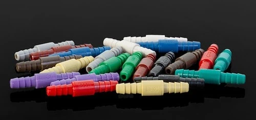
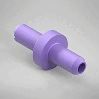
Posted by John Hayden on | Comments Off on Orifice Restrictors – Types and Applications
Black orifice restrictor vented to the atmosphere provides a controlled leak rate in the circuit.
Orifice restrictors regulate the flow of air, gases, or liquids in a variety of applications, from pneumatic control systems to coffeemakers. They are designed and manufactured with precision holes to reduce pressure and control flow. Orifice restrictors are available as individual devices or in assemblies, kits, restrictors, or restrictor valves.
Learn more about the different types of orifice restrictors, the materials they are made from, and the industries and applications where they are used.
Types of Orifice Restrictors
Air Logic offers orifice restrictors:
Molded orifices: These are our most popular designs. Molded orifices are the simplest way to provide flow control, and the different diameter sizes are color-coded.
Orifice Inserts: Subset of molded orifices, smallest option, no tubing required, push into an assembly
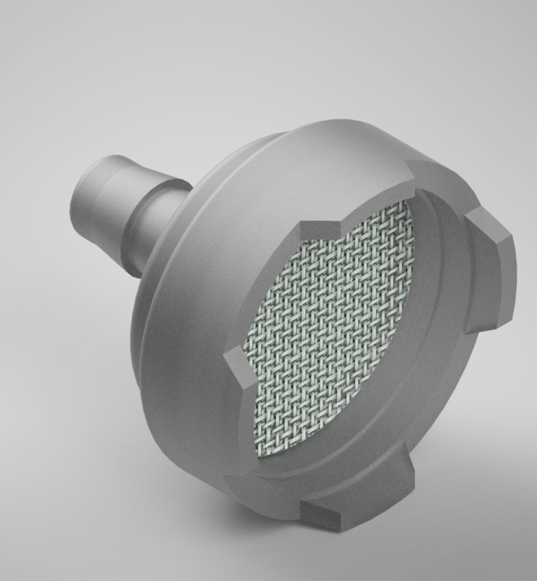
Filter orifices: These types of orifices are used to reduce upstream contamination. The integrated stainless steel filter in the precision-molded orifice can be customized for specialized applications.
Threaded orifices: With threaded fittings, these orifices can be easily installed into the pipeline. They are available in polysulfone material and can be customized.
Directional flow controls: These orifices use disks to restrict the flow of material in one direction and allow flow in the other. The flow adjusts automatically depending on the direction of the flow.
Orifice Restrictor Applications
Orifice restrictors are crucial devices in numerous applications. Find out more about them below.
Medical
Orifice restrictors play an important role in many medical devices. These orifices need to provide high levels of reliability and meet hygienic standards. Common devices and equipment that use orifice restrictors include:
Analgesia equipment: This device administers a mild inhalation anesthetic for sedation. It relies on orifice restrictors for proper flow management.
Anesthesia machines: Anesthesia machines use sanitary orifice restrictors to control flow.
Diagnostic equipment: When diagnostic equipment needs to regulate the flow of a liquid or gas, an orifice restrictor is used.
Environmental controls: Medical laboratories demand strict environmental controls to minimize the risk of contamination. Certain pieces of equipment that control air variables depend on orifice restrictors.
Dental equipment: When administrating nitrous oxide, dental equipment uses orifice restrictors to control the rate of flow.
Gas control systems: From oxygen respirators to nitrogen-powered surgical tools, the medical industry relies heavily on gas control systems. Orifice restrictors properly manage gas flows and pressures.
Gurneys & hospital beds: State-of-the-art gurneys and hospital beds have orifice restrictors to control airflow.
Hydraulic pneumatic control systems: From research labs to pharmaceutical manufacturing, hydraulic pneumatic control systems are found throughout the medical industry. These systems depend on orifice restrictors to regulate flows of different media.
Consumer Products
If a consumer product requires the flow of liquid or gas, there is a reasonable chance that an orifice restrictor can be found in its components. From coffeemakers to CBD/THC distillation products to chemical cleaning products to ozone cleaners, the average American household is full of orifice restrictors. While many consumer products use orifice restrictors to manage flow rates and pressure drops, they can also help prevent cavitation and reduce noise levels.
Life Science
The life science industry is full of machinery and equipment that depend on orifice restrictors. Much like the medical industry, high levels of sanitation are required. Common devices that utilize orifice restrictors include:
Analytical machines: Analytical machines that need to regulate the flow and pressure of gas or liquids incorporate orifice restrictors.
Bioreactors: Bioreactors are used in countless applications, including processing food, feed, pharmaceuticals, and chemicals. All of these will need to control pressure and flow to varying degrees, so they use orifice restrictors.
Gas detection: Gas detection systems need air to easily flow without causing problems related to pressure or cavitation. Many gas detection devices incorporate orifice restrictors for adequate functionality and longevity.
Flow cytometry: Flow cytometry is a sophisticated technique that provides a multi-parametric analysis of individual cells. In addition to using lasers and strategic light sources, this technology relies on orifice restrictors to control the flow of media.
Luminescence immunoassay analyzer: This device is used to detect the presence and concentration of specific substances in a sample. Common media include blood or urine. To control the flow of the medium and regulate pressure, this machinery uses orifice restrictors.
Electrophoresis: Electrophoresis is a common technique used to separate RNA, DNA, or protein molecules based on their electrical charge and size. This is achieved by moving the molecules through a gel or other type of matrix. Many electrophoresis machines use orifice restrictors to manage the flows and pressures of used media.
Flow Measurement
Orifice restrictor plates accomplish pressure management and flow measurement. This is done by utilizing the Bernoulli principle: the pressure downstream of an obstruction (the orifice restrictor) is lower than the pressure upstream of the obstruction. With the proper engineering and design, an orifice restrictor can be used to create reliable flow measurements.
Inkjet Printing
Inkjet printing relies on the controlled flow of ink. Sophisticated inkjet printers may apply additional materials such as enamel and other coatings. No matter the complexity of the inkjet printer, there is a good chance that it uses an orifice restrictor.
Nozzles
Nozzles use orifice restrictors to regulate both pressure and volumetric flow to meet specifications.
Pneumatic Controls
Unlike electronic controls, pneumatic control systems utilize compressed air. The compressed air system can send and receive signals to control an overall system. Orifice restrictors are a key component.
Particle Counting Devices
Particle counters are critical safety devices that are used in numerous applications, such as cleanrooms and other sensitive manufacturing environments. They test the room air for contaminants and other potentially harmful particles. As the device relies on the movement and flow of air, orifice restrictors are a crucial part of their design.
Orifice Restrictors From Air Logic
Air Logic is a leading provider of process flow products, including filters, check valves, relief valves, regulators, switches, fittings, and orifice restrictors. Our more than eighty years of success in the industry can be attributed to one common factor: quality.
If you have any questions about our capabilities, contact us. If you already have a project in mind, feel free to request a quote today.
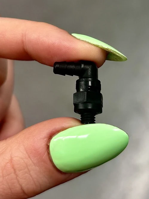
Posted by John Hayden on | Comments Off on Filtered Intake Uses: Dip Tube Filter, Suction Strainer & more!
A filtered intake is a protected entrance for a gas or liquid coming into a system or device. It has a single tube fitting attached to a filter housing or end cap, and an open filter element on the other side. Standoff geometry on the filter side of the product prevents blockage when pushed up against a flat surface. The product is a small plastic filter that can be a single-use filter, that gets disposed of with the container, or it can be fixed to the device or system and replaced as needed. Different applications of a filtered intake each have their own name for the product. The container can indicate what the filter is called. Dip tube filters are typically used in bottles. Suction strainers and pickup filters are typically used in tanks.
A Dip tube filter is meant to be submerged into a liquid and will filter out debris before it enters the system or device. It fits at the end of the dip tubing and prevents contamination from entering the system. The goal of dip tubing is to extract the maximum amount of fluid from a container or bottle. By using a bottle dip tube filter, the system may be designed in a way to hold the end of the filter up against the bottom surface of the container without blocking the flow into the dip tube. Generally, dip tubing is cut to a specific length, relatively stiff, and matched to the container that it is in. Depending on the chemical and container, these design aspects may be critical to comply with § 261.7 Residues of hazardous waste in empty containers.
What is a Suction Strainer?
Dip tube filters and suction strainers are very similar from a functionality standpoint. Suction strainers are also used to “pick up” fluid from the bottom of a container, but might not have a matched tube length and container. Commonly, a suction strainer tube will be longer and softer so that the filter rests on the bottom of the container. This type of application can accommodate a larger variety of containers but may leave more residual fluid in the container.
What is a Pickup Filter?
A Pickup Filter rests in the bottom of a refillable tank and “picks up” fluid. The filter is part of the equipment and is replaced on a maintenance schedule. Examples: Filter pickup in a fuel tank on a small engine. Filter pickup in a window wash container.
How to specify a Filtered Intake
Filter mesh size – Start here!
The first criterion to specify in any filter is the filter mesh size, which determines the particulate size that the system will be protected against. First, determine the minimum particulate size that will have a negative impact on the overall system. Then pick a filter mesh size that is a little smaller. This way, the filter will prevent any particulates from entering the system than might impact the performance.
Tube ID – Match with barb size
Match the bottle dip tube filter with the dip tubing size. A common dip tubing internal diameter (ID) is 1/8″. This can vary depending on the flow rate and viscosity of the fluid in the system.
Flow rate control – Extremely useful in some applications
In some cases, it may be advantageous to integrate a flow restrictor orifice into the filtered intake. This will control the rate at which fluid can be sucked or drawn into the system. We offer a range of sizes to suit your needs, check out our catalog page. It is possible to error-proof the flow rate of a liquid this way. Interested in some examples of how to use an orifice restrictor in your application? Check out this article!
Air Logic’s Filtered Intake
At Air Logic, we make filtered intakes that are used in a range of applications. They are small plastic filters produced in Racine, Wisconsin. Dip tube filters for bottles are the most common. Other applications include pneumatic intake filters for miniature pumps and automatic milk frothers. We work with customers who have unique filter needs and produce solutions for them. We customize features like filter mesh, plastic material, or custom flow rates (orifice restrictors). The color of the product indicated the filter mesh size. The color of the flow restrictor orifice (if included) indicates the flow rate. Check out our Filtered Intake Catalog page!
Air Logic’s Dip Tube Filter is designed to allow the dip tube to be positioned as close as possible to the bottom of the bottle. The stand-offs at the bottom of the filter allow for a flush mount while not restricting flow to the dip tube. Due to this, our design allows for a complete evacuation of the bottle while straining particulates and protecting the system.
Air Logic has experience with a range of filter products. Our filtered intake is ultrasonically welded together on automated equipment for a high-quality bond every time. Lot control is maintained from assembly through delivery to ensure quality.
If you have any questions about this filter or other small plastic filters, please reach out!
Posted by John Hayden on | Comments Off on How to Use a Pressure Switch: 3 Examples
A pressure switch is a device that is used to detect and monitor the pressure in a variety of applications. On this page, we will show you how to use a pressure switch in three different ways: by detecting an active pressure circuit, detecting a loss of flow, and monitoring upstream air pressure. We have videos that demonstrate how each of these switches is plumbed into the circuit and how they work. Pressure switches are versatile devices that can be used in a variety of applications! Check out Air Logic’s Pressure Switch Catalog.
How a mechanical pressure switch works
Pressure switches rely on changes in pressure to actuate. When pressure on the switch’s diaphragm increases, it starts to compress a spring. That spring is calibrated to compress only beyond a certain pressure rating, or the setpoint. Once the spring compresses beyond that point, the switch will trip. Pressure switches can either close normally open (NO) electric contacts or open normally closed (NC) contacts. Learn more: https://air-logic.com/pressure-vacuum-switches/
Example 1: Detecting an active pressure circuit
The way it works and how it is plumbed into the system
In this video, the red right is connected to the (NC) normally closed circuit. The green light is connected to the (NO) normally open circuit. The idea is to use the green light to indicate an activated pressure circuit.
For the pressure switch to actuate only when the intended circuit is energized, it must be plumbed into the correct spot. In the video, the correct spot is in between the 5-way valve and the check valve. As the 5-way valve energizes the pneumatic circuit, it pressurizes the switch and the system lights the green light. After the 5-way valve is flipped, the circuit loses pressure, the pressure switch resets and the red light is indicated.
The set point of the switch:
The pressure switch in this video is set at 18 psi, which is slightly lower than the system’s normal operating range of 20 psi. The reason for setting it that low? To avoid problems with leakage and tolerance stack-up or drift on the equipment.
Applications:
Industrial automation monitoring – Feedback on a pneumatic circuit can monitor critical operations of equipment by creating a closed-loop. Knowing if a pneumatic circuit that should have been activated was actually activated is achievable in this way.
Safety circuits – A pressure switch can indicate if circuits are energized before maintenance. The pressure switch could indicate if the equipment is in a “ready” or “not ready” status for maintenance.
Maintenance schedule – a PLC can alert a technician to perform a preventative maintenance action after a circuit has been activated so many times.
Example 2: Detecting a loss of flow
The way it works and how it is plumbed into the system:
The pressure switch in this video is plumbed in between the orifice restrictor and the device that is using the airflow. The orifice restrictor is providing flow control and dropping the pressure of the incoming air. So, when the engine is running and consuming air, the pressure is low. But, if the consumption of the engine is interrupted, the pressure spikes and the pressure switch detects the rise.
The set point of the switch:
The pressure switch in this video is set at 15 psi, which is slightly higher than the normal operating pressure of this circuit under normal conditions. The differential of the switch is important in this application because the switch must reset to indicate a normal flow condition.
Applications:
Equipment monitoring – Loss of flow may indicate an equipment failure. A pressure switch can alert the system or operator of the failure.
Filtration monitoring – An increase in pressure may indicate a blocked filter. As a filter becomes blocked, the restriction in the system will increase. After enough of an increase, the pressure switch can indicate a filter that needs to be replaced.
System tampering – A pressure switch in this application will be monitoring if an unauthorized increase in pressure has occurred.
Cylinder end of stroke – As a pneumatic cylinder finishes the stroke or is impeded, there will be an increase in pressure. A pressure switch can detect that increase and provide feedback to a system.
Example 3: Monitoring upstream air pressure
The way it works and how it is plumbed into the system:
The pressure switch in this video is detecting if the incoming air pressure is on. The Air compressor in the factory is in another room, so this application is to detect if the compressor is running, connected, and up to pressure. This way, it is clear the engine should run if the valve is opened. With a switch, this can be integrated into a controller and automatically monitored.
The set point of the switch:
The set point of the switch is 95psi in this application. The shop Air Pressure varies from 100-120psi during normal pressure control operations.
Applications:
Tanked gas applications – If the tank drops below the operating pressure of the equipment, the system can safely shut down.
Process control – Detect inlet pressure drops to determine if the system should be enabled or not. Inlet pressure drops may indicate a pump system failure. Compressed air systems are complicated and may have a valve turned off after the pressure tank.
Pressure Switches from Air Logic:
Air Logic has many types of pressure switches and they are highly configurable for your application. Our Mechanical pressure switch design is time-tested and reliable. We can customize the set point (operating points), spring pressure, maximum pressure, pressure port, and more. Check out our catalog!
Customer-specific specifications.
The pressure switches from Air Logic are made to order and can be shipped quickly. We can also preset the set pressure for customer applications. That way, customers can specify their product to always have the same pressure set point. Some customers specify the cut-in or cut-out pressure( ie. cut-in or cut-out point). A customer-specific test plan is made when the cut-out point or reset point is required for a pressure switch. This may also include the system pressure, a custom range spring, specific pressure, or pressure gauge usage. There can be many critical factors for your application – Please reach out if you have specific questions.
Electrical circuit specifications
There is a range of electrical ratings to match the power supply and electrical output required. Each F5100 series switch is made with a single pole double throw (SPDT) micro switch. The micro switch determines the electrical rating and performs the actual switching function. All of the electrical components are contained within the switch case. The pressure switch may be wired as a normally closed switch or as a normally open switch.
Operating principle
Air Logic’s product is a mechanical pressure switch. The air pressure from the pressure port pushes against the diaphragm (sensing element). The diaphragm (pressure-sensing element) pushes against both the spring and switch contacts. The spring force determines the set point. Adjust the spring force by turning the adjustment screw in or out. Mechanical pressure switches are straightforward and easy to implement in many system designs. Diaphragm switches are another way to describe Air Logic’s pressure switches.
Pressure range
The pressure range of a pressure switch may be important for pressure control or process control in your application. The fluid pressure setpoint must be lower than the maximum setpoint to make the switch work.
Low-pressure switches
Low pressure is a relative term that applies differently depending on the industry. A typical pressure switch from Air Logic will have an operating pressure range from 1-100psi. We can also make switches that work at lower pressures or even at negative pressure.
Posted by John Hayden on | Comments Off on Fittings – A Selection Guide | Air Logic
Pneumatic and fluidic systems use all types of components to achieve their design intent. Fittings are the components that connect everything in the system together. It is important for the connections to fit both the mechanical and functional needs of the overall system.
Find out more about pneumatic fittings, their benefits, factors to consider when selecting the right one, and the available types.
What are Fittings?
Pneumatic fittings are components used to connect pipe, tube, and hose sections in pneumatic systems. They can be applied across various applications, including medical devices, analytical equipment, chemical dilution, and biofabrication. Many pneumatic fittings are also used for fluidic and fluid delivery systems such as ink delivery or coffee makers.
While pneumatic fittings may be overlooked in the overall pneumatic system design, they are perhaps one of the most important elements. They connect valves and all other major components and deliver leak-free pneumatic movement.
With so many fittings types available, you need to consider several factors when selecting the rightoption for your needs:
Fitting material. Fitting material is crucial in determining gas compatibility and several physical properties of the part. Common fitting materials include stainless steel, brass, and thermoplastic.
Tubing dimensions. It is best to select the tubing size first, and then select a matching fitting to the tube size.
Pressure. Pneumatic fittings are often rated for certain operational pressure ranges based on equipment specifications and what it’s designed to do. A good rule of thumb is for the fitting to match or exceed the tubing pressure rating.
Thread type and base seal type. You have to consider the thread type required for your application. For example, you could need pipe thread, British pipe thread, metric thread, or SAE Straight Thread.
Approvals required. In some application use cases, you may need to install a fitting which conforms to an industry or safety standard such as NSF (National Sanitation Foundation), MDR (Medical Device Reporting), or FDA.
Static or Swivel. A swivel fitting can adjust its position after installation which is convenient for assembly. A Static fitting is fixed and cannot be adjusted after installation.
Special note for barbed fittings – The hoop strength of the tube holds around the barbed fitting. We specify our barb sizes for common applications, but it is also common for fittings to be used outside of their specifications depending on the tubing durometer and thickness.
Types of Fittings Based on Function
At Air Logic, we provide a wide collection of pneumatic fitting types for you to choose from:
Swivel Fittings with Integrated Base Seal
These fittings attach tubing to a threaded hole. The barb and tubing are able to freely rotate from the base, while the integrated sealing bead offers an affordable and convenient seal against the mating component.
Swivel Fittings with O-ring Base Seal
Air Logic’s swivel fittings with an O-ring base fasten tubing to a threaded hole. The O-ring provides a high-quality seal against the mating part, while the barbed connections offer a clean, cost-effective means of connection.
Swivel Fitting Specs:
For tubing ID ranges in inches: 0.170, 1/16, ⅛, 3/32
Wetted materials:
Body: Nylon, PP, PVDF
Elastomer options: Buna, Silicone, EPDM, or Viton
Type: Swivel Elbow, Swivel Straight, Swivel Tee
Bulkhead Fittings
Air Logic’s bulkhead fittings create a tubing path through a panel and provide connections on both sides. They are often usedas tubing adaptors to change the tubing size inside. Air Logic provides the nuts with every bulkhead fitting.
Specs:
For tubing ID ranges in inches: 0.170, 0.170 to 1/16, 0.170 to ⅛, 1/16, ⅛, ⅛ to 1/16
Wetted materials: Nylon, Polypropylene
Type: Bulkhead
Static Fittings
Static fittings attach tubing to other tubing or threaded connections. Their barbs do not have a parting line to ensure a good seal.
Specs:
For tubing ID ranges in inches: 0.170, 1/16, ⅛, ⅛ to 1/16
Type: 10-32 Threaded Fitting, Cross, Elbow, Plug, Tee, Union
Pneumatic Fittings from Air Logic
Air Logic offers a full line of pneumatic and vacuum control fittings and equipment. We are committed to excellence and quality, and our Quality Management System is ISO 9001:2015 certified. Each element of our business ensures that Air Logic delivers quality products that meet or exceed our customers’ performance expectations. For more information about our selection of fittings, or for help determining which option is right for your needs, contact us today or request a quote.
Posted by John Hayden on | Comments Off on Precision Orifices – Why Are They Needed?
Precision orifices are small devices used to accurately and consistently control the flow of a liquid or gas through a tubing system. They’re found in a diverse range of products, from coffeemakers to complex and critical systems for the aviation and aerospace industries and the delivery of anesthesia and other medical applications.
What Are Precision Orifices?
Precision orifices, also known as flow restrictors, perform exactly that job—providing a regulated, precise, consistent flow, controlling the speed and volume of a liquid or gas that passes through a system. At its most basic premise, a precision orifice is a solid part with a carefully measured hole in it through which liquid or gas flows.
The opening, typically 1/8″ or smaller, controls and regulates the passage of the liquid or gas to create a steady, accurate stream with a consistent flow for reliable, repeatable results. Careful measurements are needed to select or design a flow restrictor with the correct size, shape, diameter, material, and features to ensure the desired functionality and appropriate material for environmental conditions and the substances with which the orifice will be in contact.
Some aspects of flow control offered by precision orifices include:
Flow Rate: Precision orifices provide a steady, measured, precisely-controlled volume of liquid or gas flowing through a system.
Flow Timing: Precision orifices can supply a consistent, predictable flow rate often critical for many pneumatic and hydraulic circuits for safety and preventing malfunctions.
Flow Ratios: Precision orifices can be installed so that multiple individual flows of gas or liquid are passed through the system to create a consistent, regulated mixture in the desired ratio.
Precision orifices can function independently, with little to no maintenance. This regularity can reduce system stresses caused by inconsistent flow regulation, improving overall system integrity, performance, and durability. This also means that systems and products which incorporate precision orifices will operate uniformly and accurately.
Precision Orifice Applications
Precision orifice fittings can be simple, have in-line orifice restrictors that create the desired flow rate, can incorporate integrated filters, create directional flow (restricted in one direction and free flowing in the other), and can be produced in standard fashion, or with barbs, threaded fittings, or as a needle valve for adjustable flows. Typical materials we use include polysulfone (PSU), polycarbonate (PC), nylon, and stainless steel. Polypropylene Applications for precision orifices include any scenario in which the flow of liquid or gas must be carefully controlled to achieve expected results. Among specific industries, uses of precision orifices include:
Industrial Processes and Automation
Because precision orifices generally work smoothly without intervention, once installed, they are an ideal solution for industrial and manufacturing processes, supporting uninterrupted and automated production.
Medical, Dental, and Scientific
Precision orifices are an ideal match for the exacting requirements of medical and scientific applications, offering reliable, accurate flow control. In the medical and dental industries, they are commonly used to regulate the delivery of analgesics, anesthesia, and oxygen, as well as supporting hydraulic elements in diagnostic, imaging, respiration, beds, and other vital equipment. Scientific laboratory equipment also relies on the consistency and precisely controlled flow of liquids and gases for proper testing, experimentation, and analysis.
Marine, Aviation, and Aerospace
From the hydraulics that power fishing boat equipment to vital controls and systems in airplanes, helicopters, and spacecraft, accurate and reliable regulation of liquid and gas flow is key. Small but critical precision orifices enable braking, actuators, HVAC systems, landing gears, and numerous other systems to work smoothly and effectively.
Plumbing and HVAC
Because they typically control heated or cooled air — as well as water, oil, and other fuels — plumbing and HVAC systems require the accurate, dependable controls provided by precision orifices. Air Logic’s history began in the HVAC industry, at the time orifices were used to control the opening of HVAC valves.
Oil and Gas
The high-pressure nature of oil and gas drilling requires dependable precision orifices which allow careful regulation of equipment controls, hydraulics, pumps, lubrication, and more.
Precision Orifices from Air Logic
At Air Logic, we offer a wide array of stock precision orifices and custom fittings to meet the exact specifications of our customers. Whatever your liquid or gas flow control needs, our expert team has decades of experience and professional expertise to provide a solution.Contact us today to learn more, orrequest a quote for your next project.


 Chemical Incompatibilities of Buna-N: Nitrile rubber is a great general-purpose elastomer, but it does not hold up well against certain chemicals. Notably, strong polar solvents and strong oxidizing agents will degrade standard nitrile. The polymer chains in Buna can be broken or chemically altered by these aggressive media, leading to softening, cracks, or loss of elasticity. Always check a chemical compatibility chart if there’s any doubt.
 Orifice restrictors are used in all types of miniature flow control applications. They are commonly made from plastic in high volumes. This group of products includes inline orifice restrictors that have tube fittings on each end. Orifice restrictors may also be incorporated into threaded fittings or inserted into larger assemblies.